Test Harness
Navigate to opensource-autonomous-vehicle-controller -> lib 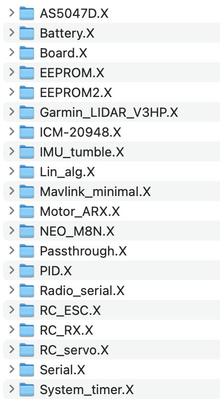
AS5047D.X contains the test harness of the encoder
- Encoder can be found here
Garmin_LIDAR_V3HP.X
- LIDAR found here
ICM-20948 contains the test harness of the IMU
- IMU found here
NEO_M8N.X contains the test harness of the GPS
- GPS found here
Radio_serial.X contains the test harness of the radio telemetry (for Mavlink)
- Radio telemetry kit found here
RC_ESC.X contains the test harness of the DC brushless unidirectional and bidirectional motors
- DC brushless motor found here
RC_RX.X contains the test harness of the radio controller
RC_servo.X contains the test harness of the servo motors
- Servo motor found here
Running the Test Harness
- Note: Before running the test harnesses, make sure that you have properly connected your peripherals
- File -> Open Project -> open-source-autonomous-vehicle-controller -> lib
- Open the folder that contains the desired test harness in MPLAB
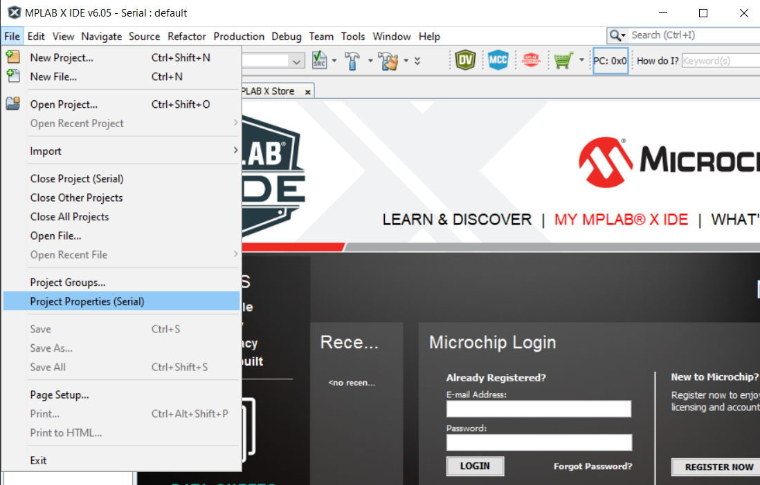
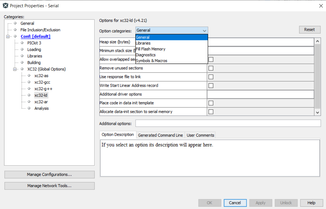
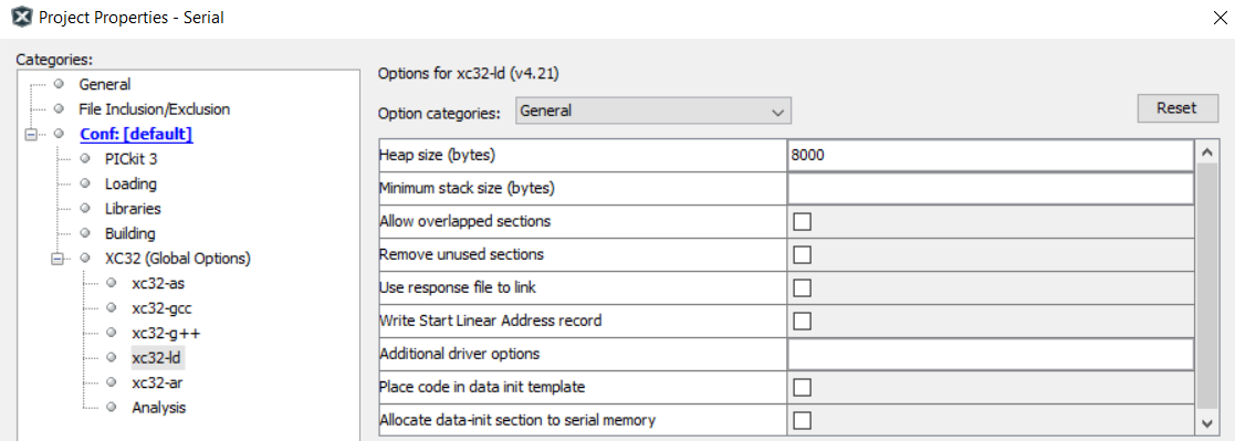
- Open the folder’s Project Properties (File -> Project Properties)
- Choose Connected Hardware Tool to PICkit3
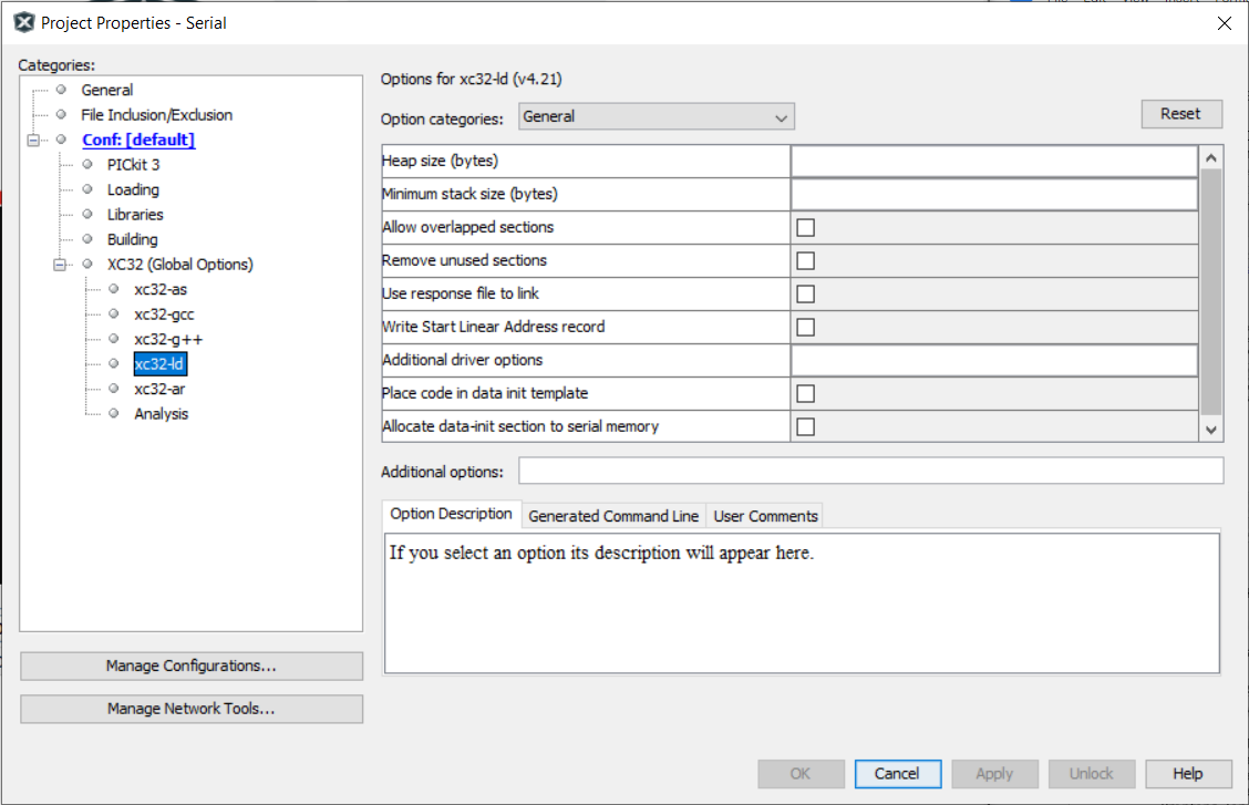
- Navigate to xc32-ld -> choose General as the option category -> set the Heap Size (bytes) to be 0 bytes
Click Clean and Build

Click Make and Program Device

Open a serial port terminal app (CoolTerm for Mac, PuTTY for Windows) and set the baud rate to 115200
IMU Test Harness
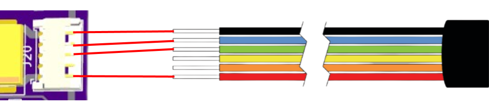
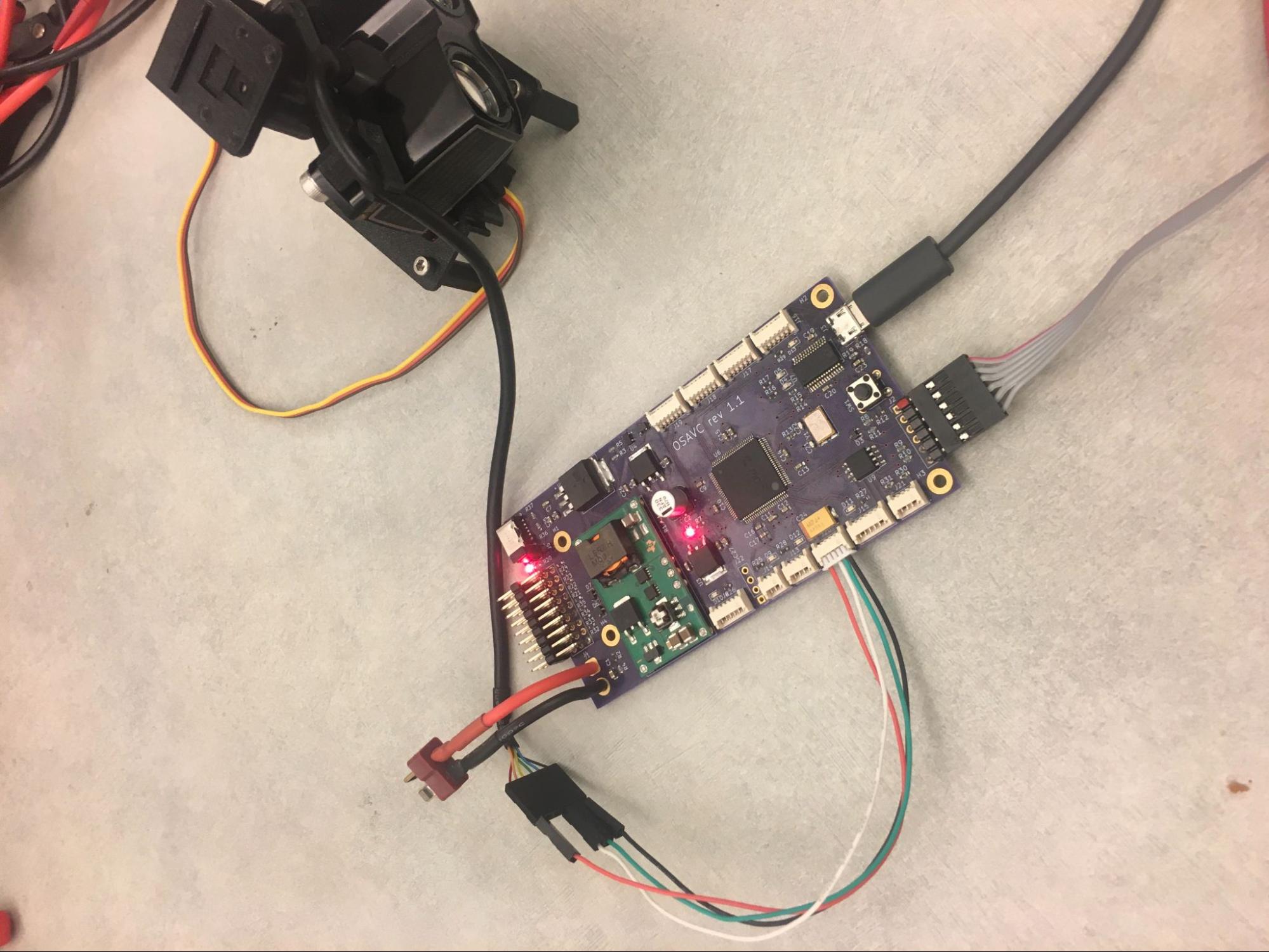
Hardware Setup for IMU
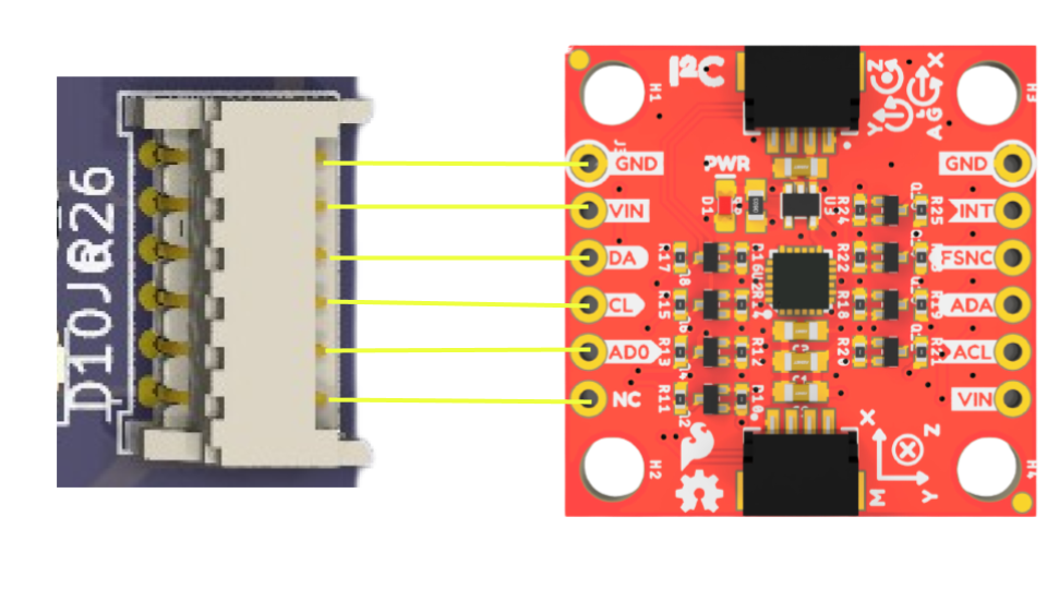
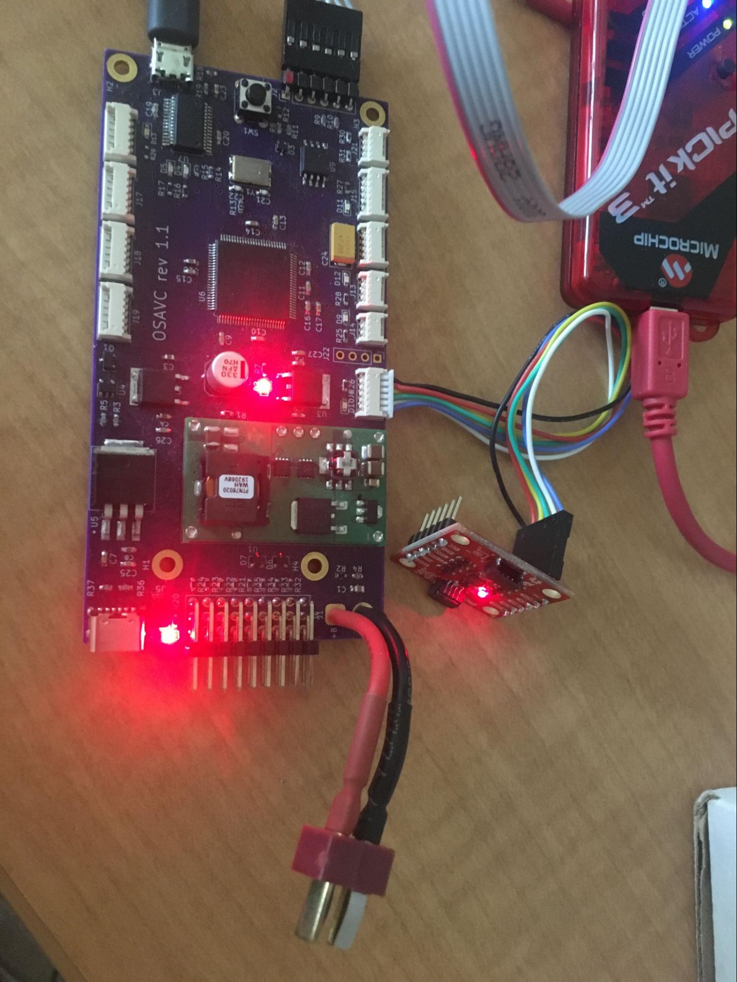
for reference to the IMU documentation refer here
Follow the steps given in Running the Teat Harness.
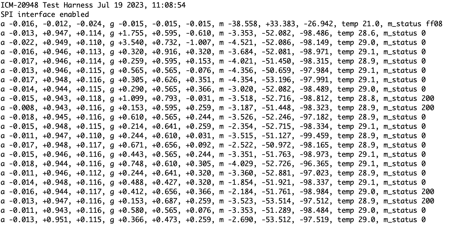
The terminal output should continuously report and update the IMU’s accelerometer, gyroscope, magnetometer readings in the x, y, and z axes, temperature, and magnetometer status. If the magnetometer status is always 0xff08, there might be an issue with your IMU:
Motor Test Harness
Hardware Setup for Motor
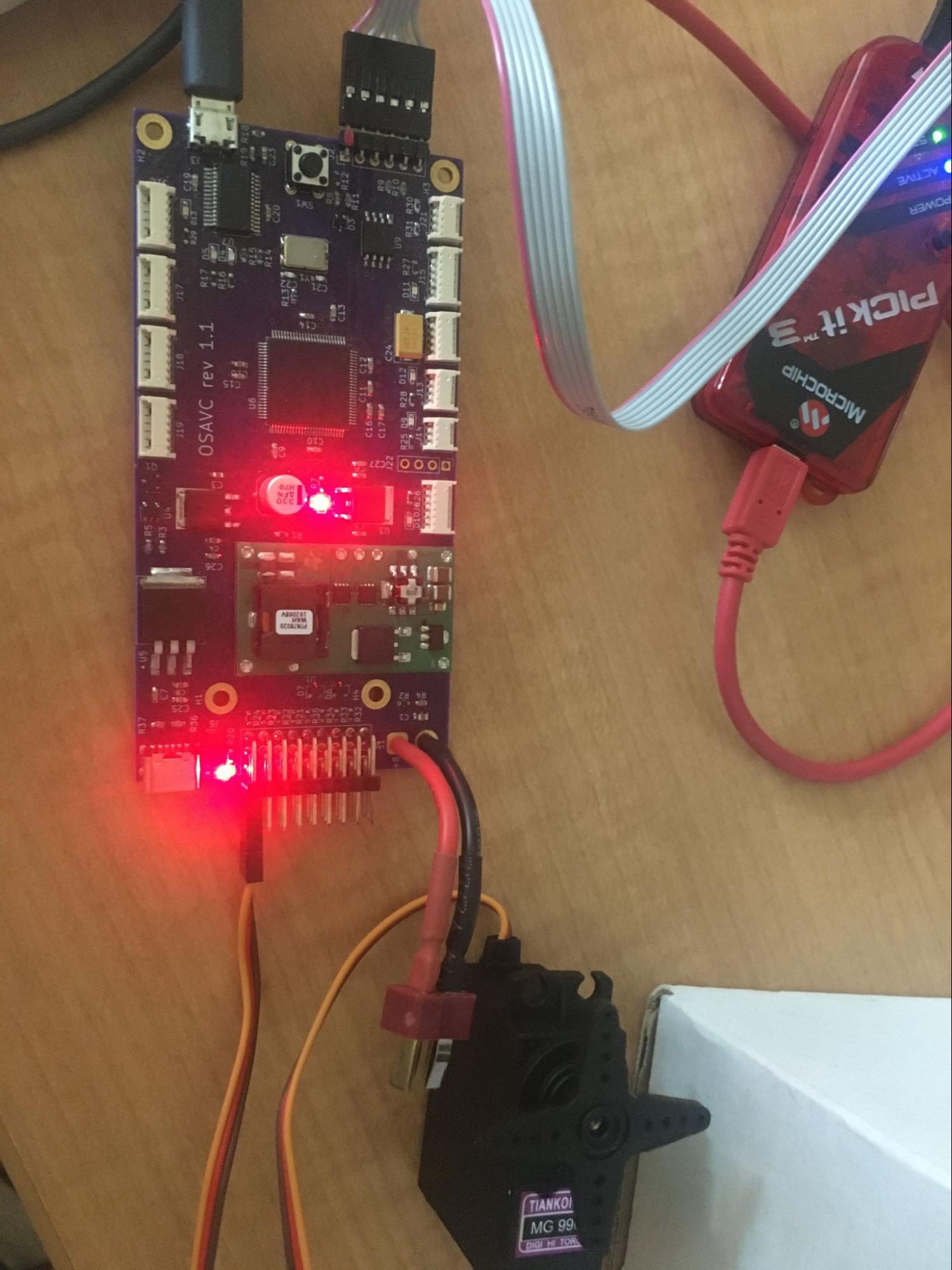
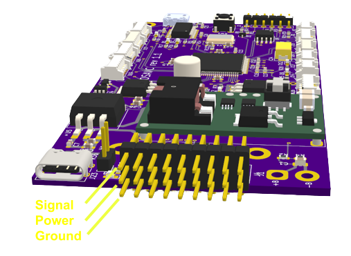
- Note : The J5 jumper must be placed to supply 5V to the power lane.
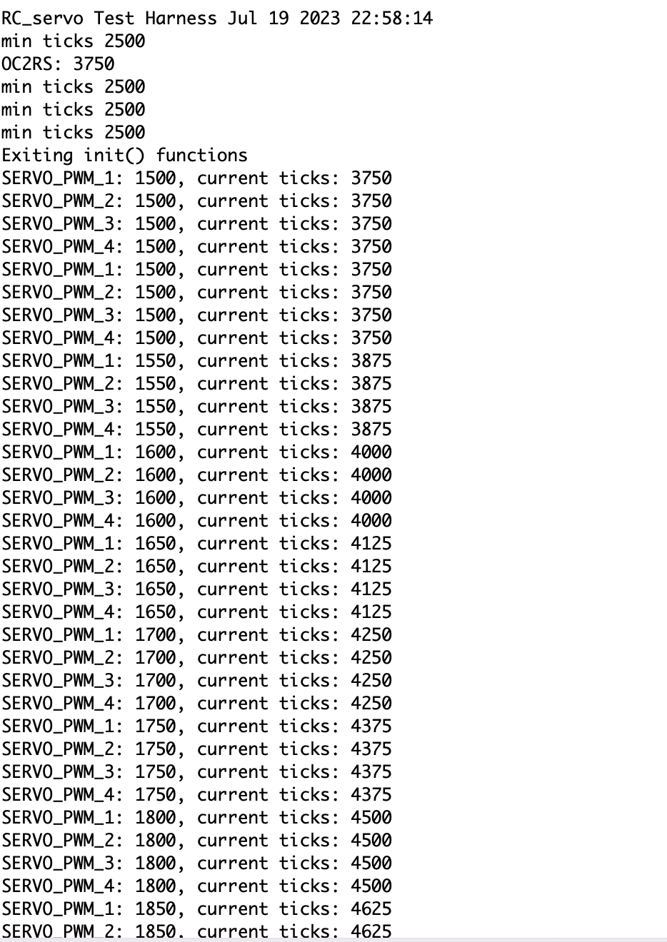
RC Servo Output
- The terminal output for the RC servo motor should be the current pulse in microseconds and the raw timer ticks.
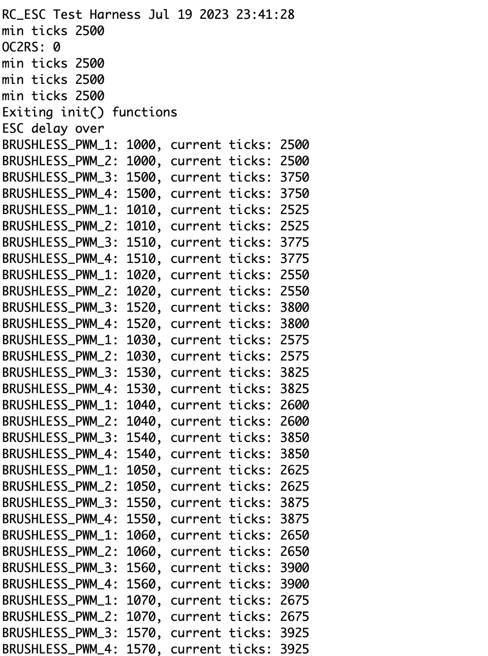
DC Brushless Output
- To calibrate a ESC unidirectional motor:
- Power it up by connecting it to a battery, and you should hear continuous beeping
- Wait for at least three beeps
- Connect to the PWM output channels in the OSAVC
- Open the RC_ESC.X folder and click Make and Program Device
- Set the minimum ticks of the motor for five seconds. This is automatically taken care of by the RC_ESC test harness.
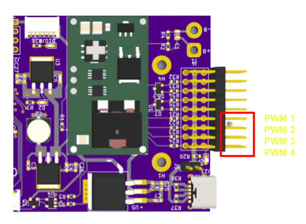
- The terminal output for the DC brushless motor should be the current pulse in microseconds and the raw timer ticks. PWM output channels 1 and 2 are for unidirectional brushless motors while PWM3 and PWM4 are for bidirectional brushless motors.
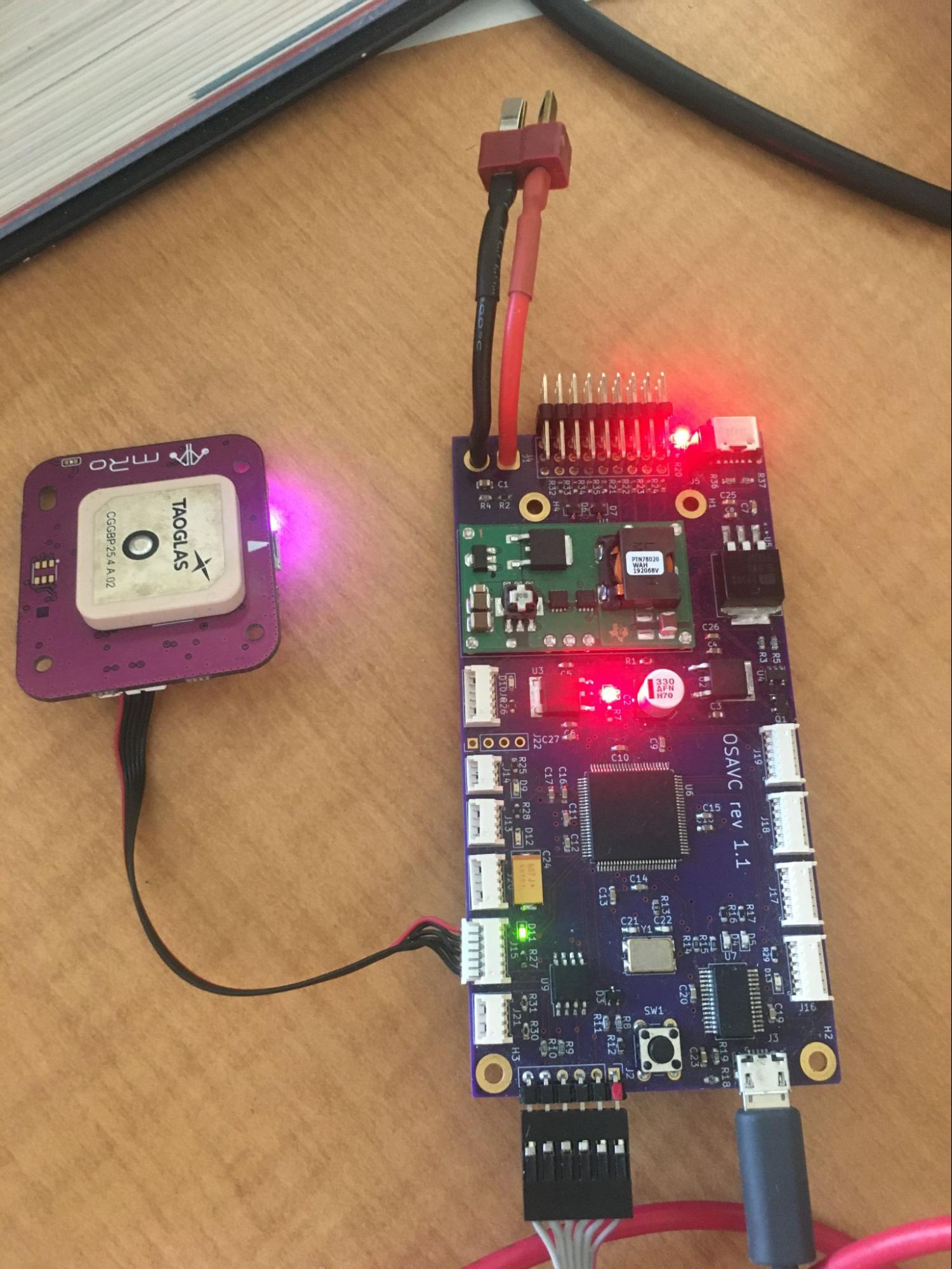
GPS Test Harness
Hardware Setup for GPS
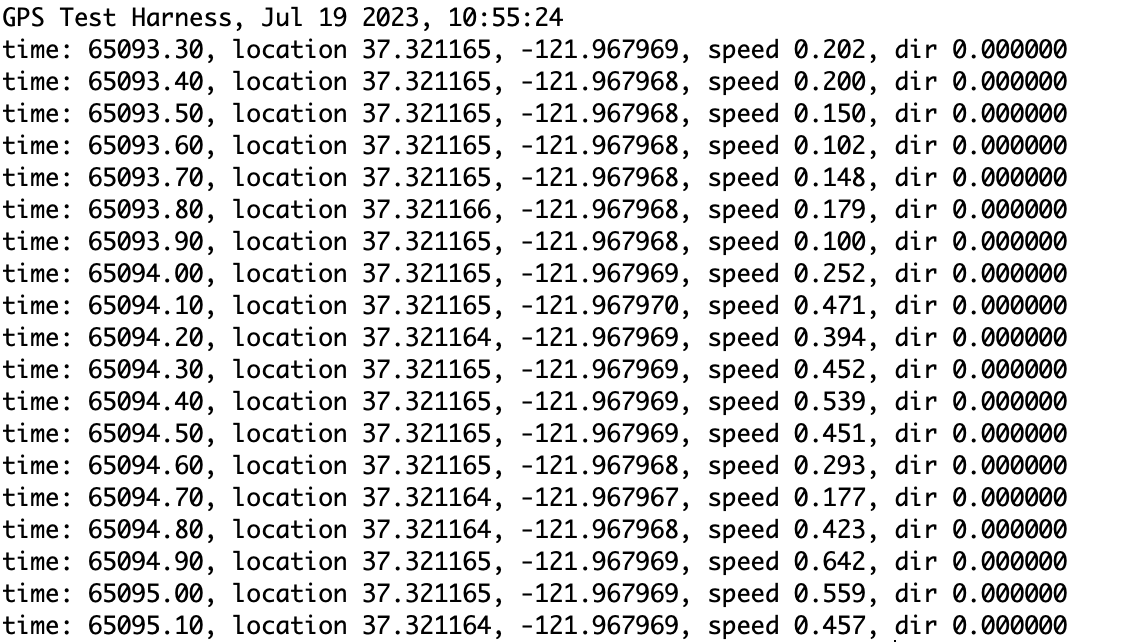
Output
- The terminal output should continuously report and update the time, latitude, longitude, speed, and heading acquired from the GPS module. Please note that the GPS module needs some time to acquire a satellite fix.
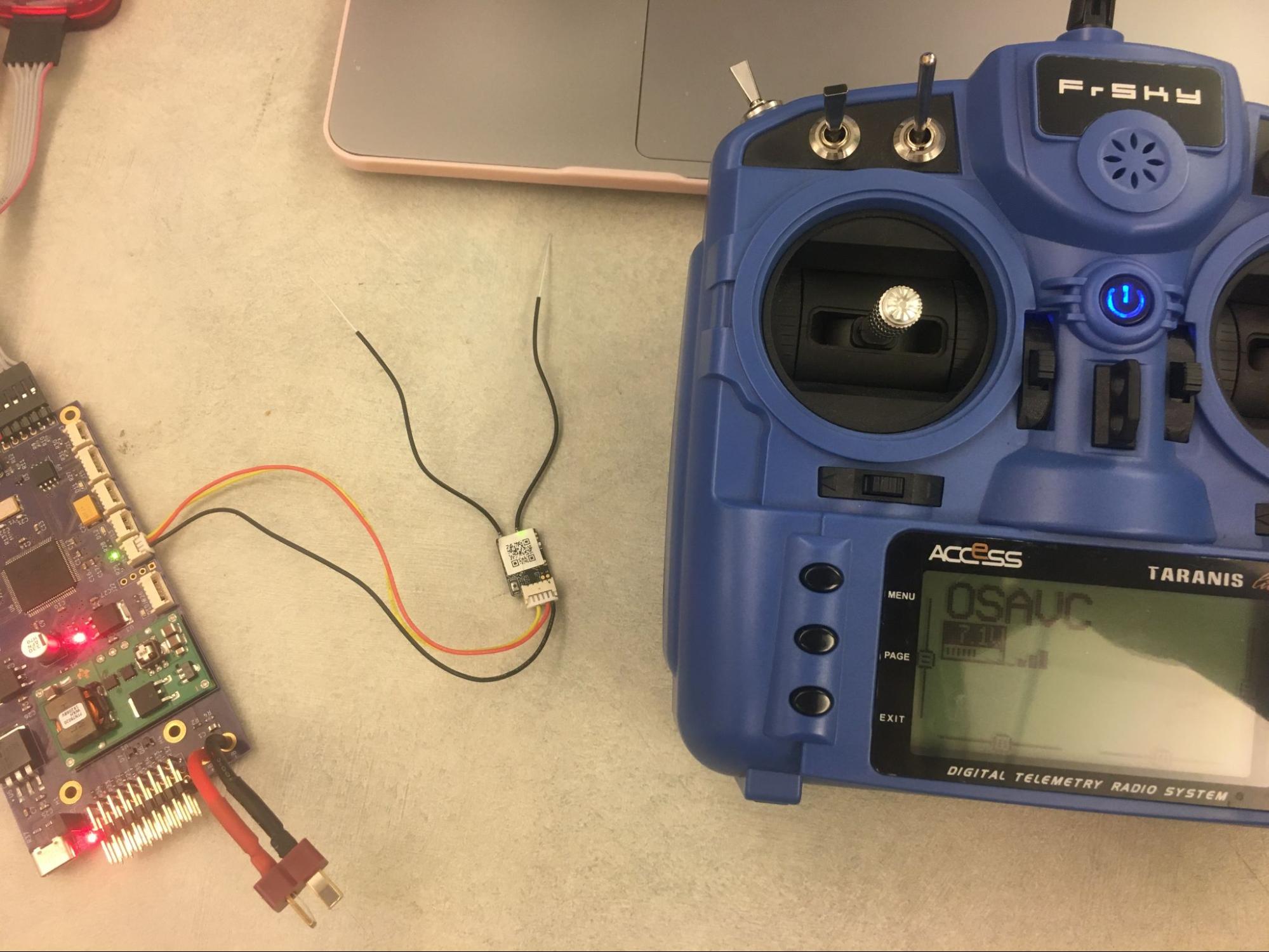
RC Receiver Test Harness
Hardware Setup for RC Receiver
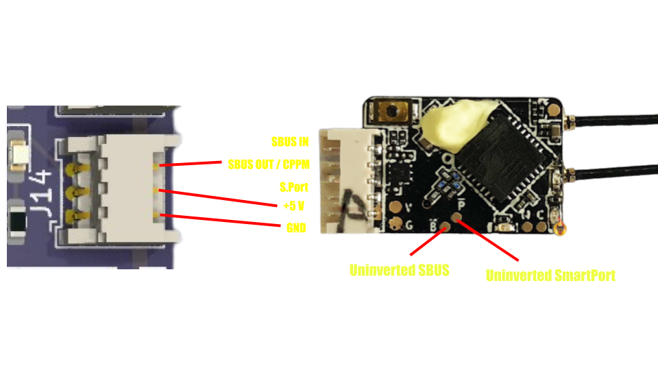
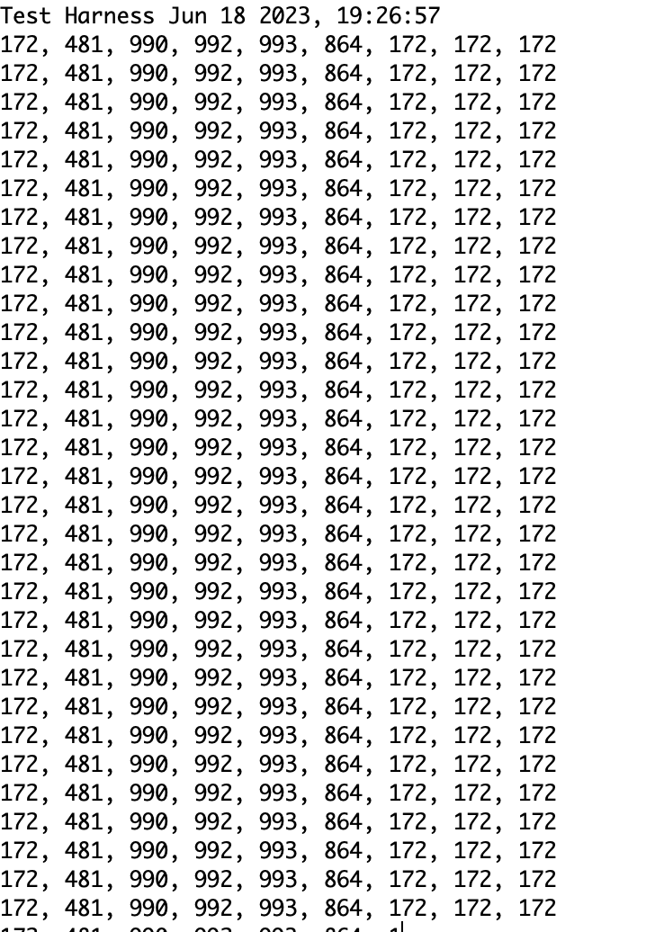
Output for RC Receiver Test Harness
- The terminal output should continuously report and update the user input to the nine channels of the radio transmitter.
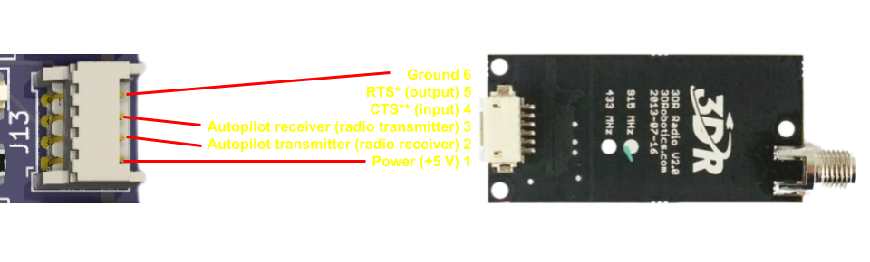
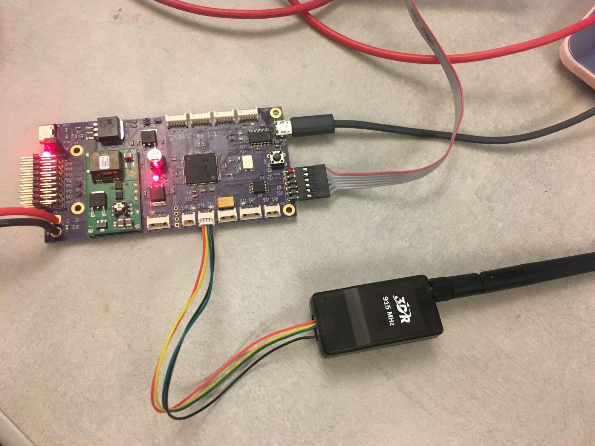
Radio Telemetry Test Harness
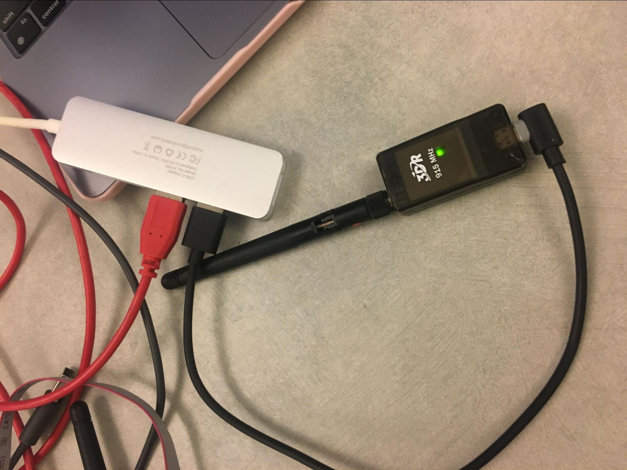
Hardware Setup for Radio Telemetry
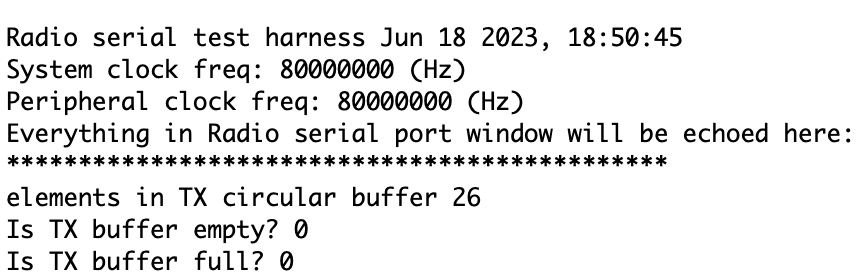
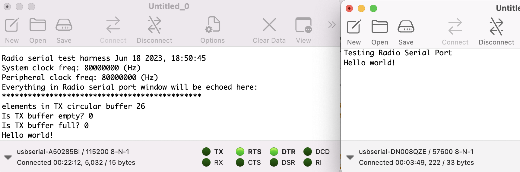
Output for Radio Telemetry
- The terminal output should show a message like this.
- Then, click File -> New to open a new terminal.

- Set the new terminal’s port to be the other usbserial (of the radio module, not the OSAVC serial port).
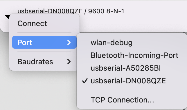
- Set the baud rate to be 57600

- Click Connect at the top of the application
- Now, type a message like “Hello world” in the new terminal, and the message should be echoed in your original terminal.
Encoder Test Harder
Hardware Setup for Encoder
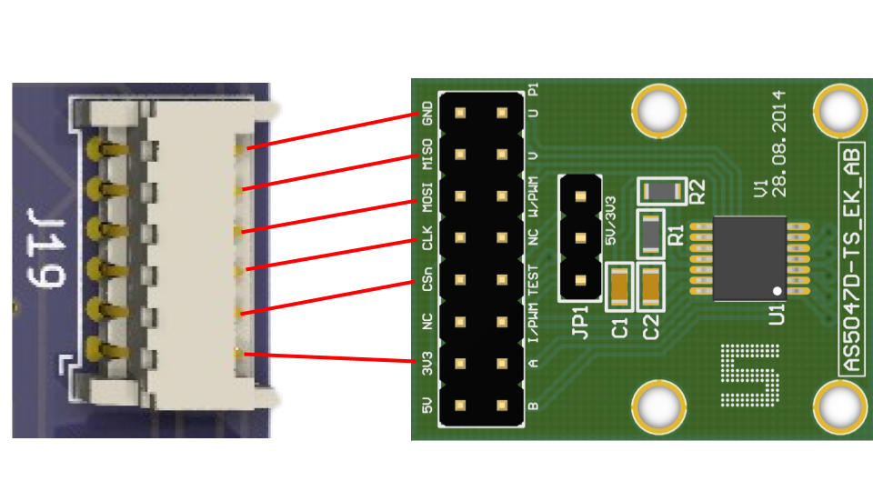
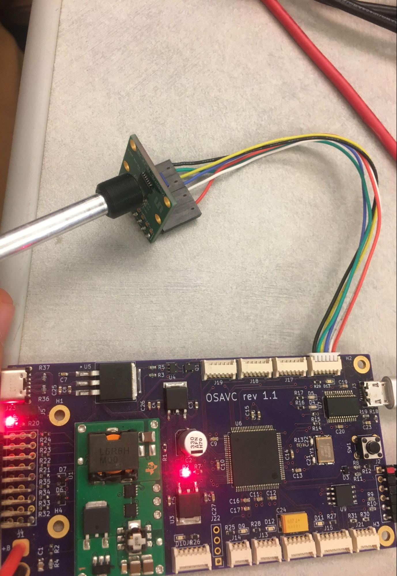
Note : If you only have one encoder, set NUM_ENCODERS to be 1 in the AS5047D.h file and connect your encoder to the J16 port.
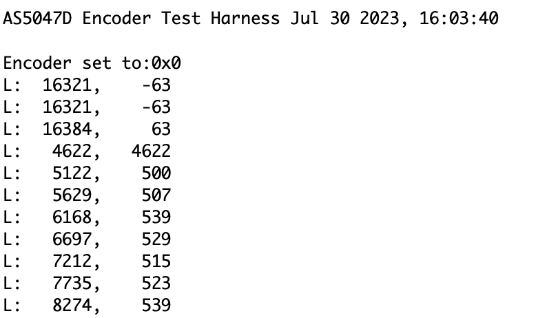
- The terminal output should continuously report and update the angle and velocity measured by the encoder in native units (16384 pulses per revolution).
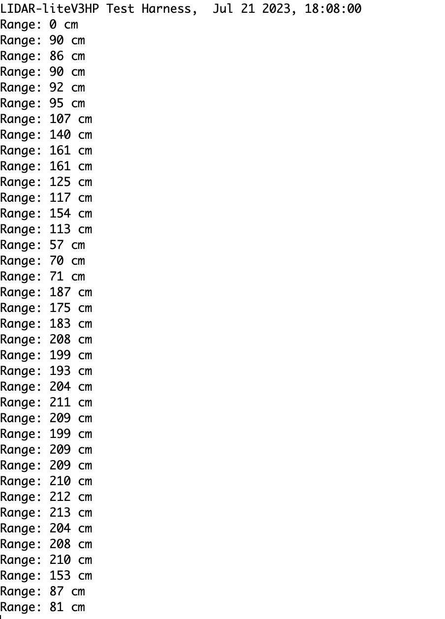
LIDAR Test Harder
Hardware Setup for LIDAR
Output for LIDAR Test Harness
- The terminal output should continuously report and update the range measured by the LIDAR sensor.